I have been doing a lot of thinking, and thanks to this blog, it has been out loud.
The PIC Microcontroller needs an interface to talk to a computer. Using USB has some perks, namely being very convenient, but it requires a lot of overhead. Based on my experience, you need special drivers for the computer, a lot of extra special code on the microcontroller, and it isn't all that reliable anyway. There might be some special configuration that works the best, but it would require some leg work. Trouble is, that leg work could be for nothing, if it keeps changing, and is drastically different for each device. I would like something that is more stable and universal, with out a lot of extra over head.
RS-232 just might be that answer. Most computers already have that capability built in, and I do not need a device driver just to have the computer talk to the PIC. The code size on the PIC is much smaller, and while the way you program a microcontroller might be different for each, they are much more transparent in how it is done.
I have some more research material below. Time to read up!
Open Directory on the PIC
Wikipedia on the PIC has information on hardware and software to program the PIC.
PIC18F4455 data sheet indispensable in information.
ICSP programmers for PIC
Wikipedia on LED has information on types and powering LED.
Wikipedia on LED Power Sources powering LED.
http://www.linkedin.com/in/andrewvall
http://www.elance.com/provprofile?userid=184021&rid=3QOZ
Electrical Engineer, Minneapolis, Minnesota
Thursday, November 25, 2010
Monday, November 22, 2010
Low Pass Filter
After some deliberation, I have decided to not use an RLC circuit, and to go with an active, two pole, low pass filter.
 I think it would be simplest to use Nodal Analysis, with two unknowns, and two equations. The use of conductances can make nodal analysis much easier, so I think I will use that. The conductance is simply the reciprocal of the resistance.
The first nodal equation:
 The second nodal equation:
 Solving the second nodal equation for V1:

 Substituting this into the first nodal equation:


Simplifying

 Solving for V2, which is the output:
 Combining like terms:


 Where omega is the cut off frequency, and Q is the gain of the amplifier at omega. For the best possible filter performance, while remaining maximally flat, Q should be between 0.707 and 1. I do not want the gain to roll off too quickly, nor do I want too high of a peak at the cut off frequency.
R1 and R2 should be on the same order as the output resistance of the microphone, C1 could equal C2. If that is the case, the equations simplify.

 Unfortunately, this configuration can only produce a Q of 0.5, and only with equal resistances. To simplify the number of components needed, both resistances will be equal.

 C1 must be between two and four times C2 to achieve a high enough Q. The resistance is 1000 Ohms.
With C1 two time C2, and R equal to 1000 Ohms

 C2 is 100 nF, C1 is 200 nF.
Looking at the simulation, in log log scale, I see that it does not roll off at a low enough frequency. I choose C2 to be 200 nF, and C1 to be 400 nF. Now the drop off starts at 200 Hz, instead of at around 700 Hz.
In conclusion, this is the operation of the active, two pole, low pass filter. Unlike the RLC, higher resistance smaller capacitances can achieve smaller cut off frequencies. Care must be taken to make sure operational amplifier non-linearities are properly accounted for, but this is a valid way of implementing a low pass amplifier.
http://www.linkedin.com/in/andrewvall
http://www.elance.com/provprofile?userid=184021&rid=3QOZ
Electrical Engineer, Minneapolis, Minnesota

The first nodal equation:
Simplifying

R1 and R2 should be on the same order as the output resistance of the microphone, C1 could equal C2. If that is the case, the equations simplify.
With C1 two time C2, and R equal to 1000 Ohms
Looking at the simulation, in log log scale, I see that it does not roll off at a low enough frequency. I choose C2 to be 200 nF, and C1 to be 400 nF. Now the drop off starts at 200 Hz, instead of at around 700 Hz.
In conclusion, this is the operation of the active, two pole, low pass filter. Unlike the RLC, higher resistance smaller capacitances can achieve smaller cut off frequencies. Care must be taken to make sure operational amplifier non-linearities are properly accounted for, but this is a valid way of implementing a low pass amplifier.
http://www.linkedin.com/in/andrewvall
http://www.elance.com/provprofile?userid=184021&rid=3QOZ
Electrical Engineer, Minneapolis, Minnesota
Wednesday, November 17, 2010
RLC
I am trying to find a simple RLC filter, with few components. The component values should be readily available and not too large.
Their are two flavors of the RLC low pass filters. One is where the resistance is in series with the inductor, the other is where the resistance is in parallel with the capacitance. What happens when these two flavors are combined?
 The equivalent resistance between R2 and C1 is as follows.
 The output is just a voltage divider.
 What can I see intuitively from this equation? Well, when s or j omega equals zero, the output is simply the input times a voltage divider. Omega squared is simply the capacitance times the inductance.
Can the equation be simplified? The inductance should be very small, so the middle term should simplify.
 I would like the filter to be critically damped. When does that happen?
 When the radical equals zero, it is considered to be critically damped, where the system returns to equilibrium as soon as possible, with no ringing or oscillations.
 If R2 is much greater than R1, then the radical can be further simplified.

The radical must to equals zero.
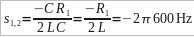
 If the capacitance equals the reciprocal of R1, then the roots are simply this.
 But this creates a problem. R1 should be very small. This means that C would need to be relatively large, which we don't want. Thus, I will keep the root as it was.
 Because R1 equals 1 kilo Ohm, L equals 0.1 Henry. Even if R1 equals 1 Ohm, the inductance would still be 0.1 mH.
I have come to the conclusion that RLC low pass filtering circuits are best used for attenuating very high frequencies.
It seems my best option is to use an active low pass filtering circuit. This way, the output resistance of the microphone will not effect the filtering equations, I can use much smaller values, and I can make the filter PCB foot print relatively small, even if the part number is relatively large.
http://www.linkedin.com/in/andrewvall
http://www.elance.com/provprofile?userid=184021&rid=3QOZ
Electrical Engineer, Minneapolis, Minnesota
Their are two flavors of the RLC low pass filters. One is where the resistance is in series with the inductor, the other is where the resistance is in parallel with the capacitance. What happens when these two flavors are combined?

Can the equation be simplified? The inductance should be very small, so the middle term should simplify.

The radical must to equals zero.
I have come to the conclusion that RLC low pass filtering circuits are best used for attenuating very high frequencies.
It seems my best option is to use an active low pass filtering circuit. This way, the output resistance of the microphone will not effect the filtering equations, I can use much smaller values, and I can make the filter PCB foot print relatively small, even if the part number is relatively large.
http://www.linkedin.com/in/andrewvall
http://www.elance.com/provprofile?userid=184021&rid=3QOZ
Electrical Engineer, Minneapolis, Minnesota
Monday, November 15, 2010
The Filter
The frequencies of interest are under 600 Hz. I need to put a filter just after the microphone to attenuate the unwanted frequencies. I would like this filter to take up as little PCB real estate as possible, make it very small and simple.
I would like a second order low pass filter. A passive RC network is the simplest, but is first order. A second order RC network contains at least four components, and also attenuates the passband.
An active filter has a second order implementation, but is much more complex. I would need to supply power to the active devices, the foot print would be much larger, and there would be more parts to fail. I would rather not use any of these implementations.
The simplest second order filter possible is likely an RLC filter. To make a low pass, second order configuration, the inductor is in series with the signal, the capacitor is in parallel with the signal. The inductor is a short to small frequencies and is an open to large frequencies. The capacitor is an open to small frequencies, and a short to large frequencies.
The input is a 1 kilo Ohm resistance microphone, CMB-6544PF. The output is an infinite impedance amplifier.
This is the circuit. The one kOhm resistor is part of the signal source. This creates a difficulty.
 Converting L and C to their equivalent S domain impedances.
 Equating terms.
 and
and
 So, accordingly.

 There lies the problem. Because the output impedance of the microphone is so large, the resulting inductance is very large. To have an inductance that has an economical value, the resistance would need to be very small. An inductance of this size is likely to be very large, and have a lot more problems associated with it.
After some thought, a first order RC filter seems the best option.
 A QUCS simulation confirms that while both components are more physically realizable, the point where the attenuation reaches 10 % is at 5 kHz.
http://www.linkedin.com/in/andrewvall
http://www.elance.com/provprofile?userid=184021&rid=3QOZ
Electrical Engineer, Minneapolis, Minnesota
I would like a second order low pass filter. A passive RC network is the simplest, but is first order. A second order RC network contains at least four components, and also attenuates the passband.
An active filter has a second order implementation, but is much more complex. I would need to supply power to the active devices, the foot print would be much larger, and there would be more parts to fail. I would rather not use any of these implementations.
The simplest second order filter possible is likely an RLC filter. To make a low pass, second order configuration, the inductor is in series with the signal, the capacitor is in parallel with the signal. The inductor is a short to small frequencies and is an open to large frequencies. The capacitor is an open to small frequencies, and a short to large frequencies.
The input is a 1 kilo Ohm resistance microphone, CMB-6544PF. The output is an infinite impedance amplifier.
This is the circuit. The one kOhm resistor is part of the signal source. This creates a difficulty.


After some thought, a first order RC filter seems the best option.
http://www.linkedin.com/in/andrewvall
http://www.elance.com/provprofile?userid=184021&rid=3QOZ
Electrical Engineer, Minneapolis, Minnesota
Thursday, November 4, 2010
How to put FFT in a microcontroller? 2
What do I need from a Microcontroller?
As my Windows 7 laptop has been acting up lately, I will be using Linux. While everything might not be as neatly packaged as might happen on Windows, Linux should have all the necessary packages I need. Currently I run Fedora 12. My development environment is Eclipse. There is a collection of tools for the Micrchip PIC called gputils, gpsim, and ktechlab. Both gputils and gpsim are run from the command line. Ktechlab includes gpsim functionality. Piklab is an IDE that uses gputils and gpsim. The only problem is all of these programs are in alpha and beta. I have been rather impressed with linux software to date, so I will give them a try.
http://gputils.sourceforge.net/
http://gpsim.sourceforge.net/
http://www.eclipse.org/
http://www.microchip.com/
A way of serially programming the PIC is using picprog. They also describe the hardware necessary to connect the two. This is also run from the command line.
http://hyvatti.iki.fi/~jaakko/pic/picprog.html
I decided to use the 16 Bit Core size, which knocks Digikey down to 25 pages from more than 100. I am choosing Microchip, a PIC core processor, 40 MIPs speed. There is still so much to choose from.
http://www.linkedin.com/in/andrewvall
http://www.elance.com/provprofile?userid=184021&rid=3QOZ
Electrical Design Engineer in Minneapolis Minnesota
Wednesday, November 3, 2010
How to put FFT in a microcontroller? 1
I would like to make an LED display that will flash to the beat of various music.
Here are some requirements.
I could either go digital or analog, depending what I want from the system. If there was only one range of frequencies I was interested in, with only one set of LEDs, analog would work the best, because it would be the simplest: only one filter, LED driver, and the LEDs. Because I am interested in several groups of LEDs, all controlled by a different range of frequencies, the analog solution is out. With a digital system, like with a microcontroller, I could easily program in different frequencies using a digital filter, or use an FFT algorithm, to target any set of frequencies I want. The problem with using a digital filter is that it is for only one range of frequencies. I would like each group of LEDs to be controlled by different sets of frequencies. It looks like my best option is to use an FFT algorithm, because that divides a frequency range (half Nyquest frequency divided into N samples), and quantifies that with an amplitude.
I would like to choose a Microcontroller that is fairly easy to operate, yet has enough functionality to get the job done. I have looked into the Texas Instruments Piccolo, but I have yet to see anything that would make me want to pursue it any further. It lacks a user base, all of the material comes from TI. Its documents and coding are confusing. The site says they wanted to create a microcontroller that was sufficiently easy to use, so that developers could easily apply it to their projects, but have they really done that? They have a lot of existing projects, but I don't quite see how to change those projects to fit my needs. I think I am better off going with a different microcontroller, which is what I will be researching next.
http://www.linkedin.com/in/andrewvall
http://www.elance.com/provprofile?userid=184021&rid=3QOZ
Electrical Design Engineer, Minneapolis, Minnesota
Here are some requirements.
- Their will be multiple LED groups that will have different controllers for each.
- Each group will be controlled by a different range of frequencies.
- The system must be capable of frequencies past 40 kHz.
- The whole system should not waste power.
- LED should draw little current.
I could either go digital or analog, depending what I want from the system. If there was only one range of frequencies I was interested in, with only one set of LEDs, analog would work the best, because it would be the simplest: only one filter, LED driver, and the LEDs. Because I am interested in several groups of LEDs, all controlled by a different range of frequencies, the analog solution is out. With a digital system, like with a microcontroller, I could easily program in different frequencies using a digital filter, or use an FFT algorithm, to target any set of frequencies I want. The problem with using a digital filter is that it is for only one range of frequencies. I would like each group of LEDs to be controlled by different sets of frequencies. It looks like my best option is to use an FFT algorithm, because that divides a frequency range (half Nyquest frequency divided into N samples), and quantifies that with an amplitude.
I would like to choose a Microcontroller that is fairly easy to operate, yet has enough functionality to get the job done. I have looked into the Texas Instruments Piccolo, but I have yet to see anything that would make me want to pursue it any further. It lacks a user base, all of the material comes from TI. Its documents and coding are confusing. The site says they wanted to create a microcontroller that was sufficiently easy to use, so that developers could easily apply it to their projects, but have they really done that? They have a lot of existing projects, but I don't quite see how to change those projects to fit my needs. I think I am better off going with a different microcontroller, which is what I will be researching next.
http://www.linkedin.com/in/andrewvall
http://www.elance.com/provprofile?userid=184021&rid=3QOZ
Electrical Design Engineer, Minneapolis, Minnesota
Subscribe to:
Comments (Atom)